

Random Wire 152: WPSD-M17 Community Fork works with Raspberry Pi 5! Also, step-by-step instructions for building a Raspberry Pi 4 hotspot for digital voice.
October 10, 2025: The WPSD-M17 fork works on the Raspberry Pi 5 platform! I assembled another hotspot with a Raspberry Pi 4 and documented this each step of the way.

Welcome to Random Wire issue 152. This issue opens with a great discovery of interest to those of us using M17. Farther down, the featured content is a step-by-step guide to assembling a digital hotspot using a Raspberry Pi 4 computer. In between are some “short stack” notes and a few more small items. I hope you enjoy issue 152.


IMPORTANT: WPSD-M17 Community Fork works with Raspberry Pi 5
TL;DR — The WPSD-M17 Community Fork software does work with the Raspberry Pi 5 board. The M17 wiki has been updated to reflect this.
The system compatibility list on the M17 Community Fork wiki lists several Raspberry Pi models, but not the Raspberry Pi 5:
Hardware: Raspberry Pi 3, 4, Zero 2 W, and compatible boards
Last week, I wrote about the new Hamspot 5 device and a subscriber pointed out it doesn’t work with the WPSD-M17 fork because the Hamspot 5 is based on a Raspberry Pi 5. I responded that the fork wasn’t compiled for the Raspberry Pi 5. However, this proved to be a faulty assumption. Chip W0CHP, the author of the WPSD system, responded:
Yes it is [compiled for the Raspberry Pi 5]. I wrote/write WPSD, and the M17 fork (wish they’d change the name, to avoid user confusion) does run swimmingly on an RPi 5.
This was exciting news! I dropped everything I was doing to burn a copy of the WPSD-M17 fork to a fresh microSD card. When I booted the Hamspot 5 with the new card, it booted up cleanly and I was able to configure the hotspot.
Bottom line: The WPSD-M17 Community Fork works with the Raspberry Pi 5!
Here is the new installation screen from the WPSD-M17 fork (before configuration):

Here’s the hotspot dashboard after configuring the hotspot for Yaesu System Fusion (the mode my Yaesu radio was already set up for):

After configuring the hotspot, I made a test transmission (Yaesu System Fusion mode) to the YSF Parrot to make sure the hotspot was working properly.
(Below, I cover all of the configuration settings in the step-by-step guide to building a Raspberry Pi 4 hotspot.)
I haven’t tested it with my M17 radios yet but I’m sure it will work, since my mini M17 hotspot built on a Raspberry Pi Zero 2 W platform, running the same software, is working fine.
Wojciech Kaczmarski (M17 Foundation) approved my account on the M17 wiki, so I was able to correct the information regarding compatibility with the Raspberry Pi 5.

The wiki page now shows the updated information:

Short Stack
Install Cockpit on your Raspberry Pi
I’ve learned to really like the Cockpit version of AllStarLink 3 on Raspberry Pi devices. You may not have realized that Cockpit is a general high-level dashboard for Raspberry Pi devices, not just for those running AllStarLink 3. Learn more at: https://raspberrytips.com/cockpit-on-raspberry-pi/
OpenWRT on Raspberry Pi: Turn your Pi into a router
Here’s the link: https://raspberrytips.com/openwrt-on-raspberry-pi/
OpenWrt has a custom release available on its website for all Raspberry Pi models. It can be flashed on an SD card like any other operating system. A few commands are required to configure the network on the first boot, but after that, everything can be done from the web interface.
RF remote control of WPSD hotspot
Bob AD2IZ alerted me to something I was wholly unaware of—the ability to issue control commands through WPSD and a radio to my hotspot. Oh wow!
I found an example of this in a BridgeCom PDF. And this Gist has additional information, including a set of commands that indicates this should work with a hotspot configured for DMR, D-STAR, YSF, P25, and M17. To top it off, I also found these commands in the DVMEGA Cast system:
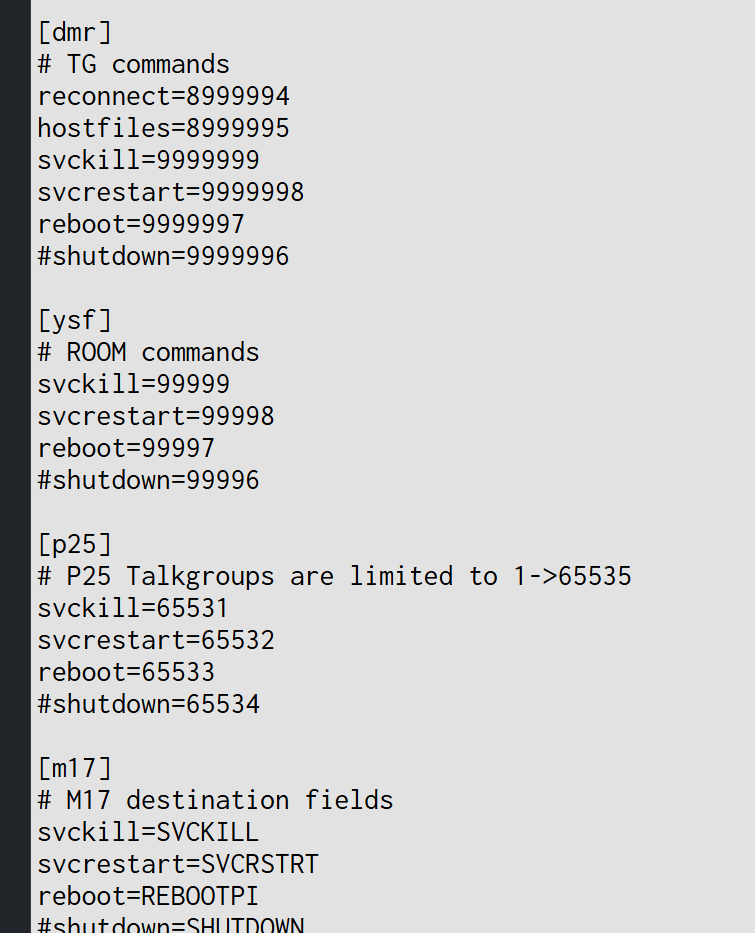
This is definitely worth exploring. I’ll be trying this.
Turn an Android smartphone into a ham radio transceiver
kv4p HT is an open-source hardware VHF or UHF radio designed to plug into the USB-C port of an Android smartphone and turn it into a handheld ham radio transceiver. It’s based on an ESP32 wireless module and an SA818 radio module. This accessory makes your phone capable of off-grid voice and text communication with a Technician-class amateur radio license. It’s small enough to fit into a pocket, partially because it does not need a battery, relying on the built-in battery of your phone.
This was available at Halibut Electronics but is listed as “out of stock.” It appears Chelegance still has stock.
Helikite for a wire antenna?
This looks weirdly cool. A Helikite is a kite balloon, or “kytoon.” Find them at the Allsopp Helikites LTD website. For the quickest overview, check the price list at https://www.helikites.com/helikite-prices. I’ll be the first to say the prices preclude most of us from trying this technology, but I’ll also say the Helikite looks like it would be a functional upgrade from a simple helium balloon, especially in a breeze.
Building A Ham Radio Data Transceiver On The Cheap
That’s the title of an article on Hackaday.com.
Once upon a time, ham radio was all about CW and voice transmissions and little else. These days, the hobby is altogether richer, with a wide range of fancy digital data modes to play with. [KM6LYW Radio] has been tinkering in this space, and whipped up a compact ham radio data rig that you can build for well under $100. Radio-wise, the build starts with the Baofeng UV-5R handheld radio.
CC1200 Hat boards for M17: Part 1
This week, I ordered CC1200 Hat boards from PCBWay.com. The minimum order of five boards ended up being surprisingly more expensive than I had expected. There is the cost of the board, plus labor for assembly, plus shipping, plus import fees, plus tariffs (here is what PCBWay says about the tariffs). My delivery address is in Washington State so tack on state sales tax, too. The cost for five boards came to $224.66.
I also had to set up a FedEx shipping account. This proved to be a bit complicated since we have footprints in two states. FedEx did not like that one little bit so I had to simplify my information to get the FedEx shipping number.
And I am hoping (fingers and toes crossed for luck) that the default configuration settings in the PCBWay order screen were correct. If not, I’ll end up with pretty boards…pretty useless!
The CC1200 hat mounts on a Raspberry Pi board, connected via the GPIO pins. Tom WB8OUE says with a Raspberry Pi Zero 2W, the package is the size of a package of gum. After installing the hat, I’ll need to load firmware and an operating system. At that point, I can begin to explore how the CC1200 works. Says WB8OUE: The CC1200 really runs well.
The boards won’t be here in time to configure and test before Random Wire 152 is published, so this will be a serialized story. This segment is Part 1.
More Linux distros tried: now using Debian 13
I tried some additional Linux distributions on the old Mac Mini. Elementary OS is a nice looking flavor of Linux. I really liked Zorin OS, even though (or because?) it looks a lot like Windows. It has some easy-to-use settings for sharing the screen. But there was a security layer that prevented me from running the computer headless, remotely, so I abandoned it.
After that, a little more Googling and I was headed toward Linux Mint, but thought maybe I ought to give the latest flavor of Debian a try. I installed Debian 13 “Trixie” and it went swiftly and smoothly. To allow remote connections via VNC, I installed x11vnc following the guide at https://tecadmin.net/setup-x11vnc-server-on-ubuntu-linuxmint/.
I was surprised that the x11vnc setup went perfectly. I was able to connect without any of the drama I’ve been having with other distributions.
I did run into a screen off situation that took some sleuthing to figure out. I would connect to the Debian 13 machine over a VNC connection, and some minutes later, the screen would go black. I tried several solutions (both through the graphical user interface and the command line) before hitting on one that seems to be working. This solution disables DPMS and screen blanking completely.
I created a new file with the nano text editor:
sudo nano /etc/X11/xorg.conf.d/10-extensions.confThen I added these lines to to the .conf file to prevent the DPMS (display power management system) from running and stop screen blanking:
Section "Extensions"
     Option "DPMS" "false"
EndSection

Section "ServerFlags"
     Option "BlankTime" "0"
EndSection
Then I saved the file (Ctrl X in nano) and rebooted. The Debian 13 machine has been up and connected to my laptop via VNC for two hours without any screen blanking. Win. It looks like the screenshot below—rather plain, but that’s Debian! If memory serves, this is the Xfce desktop environment.

The other issue I found is the Mac Mini 2014 uses a Broadcom wifi chip but Debian 12 and 13 don’t support it. There is no driver package for it. I solved that by purchasing an inexpensive USB dongle for wifi. This $15 dongle worked right out of the box:
Doubling down on these conversions from Mac operating systems to Linux, I bought a gently used MacBook Air on eBay. That will be converted to a Linux machine, too: a great looking, thin, light Linux machine. I am really amazed at how inexpensive some of these older platforms are. I’m finding them to be robust and quick enough for most of the things I do, and I do like repurposing older tech.
I have to say that all of the Linux distros I’ve tried on the Mac Mini have been pretty snappy. I really did want to keep Zorin, and I really did like MX Linux. In the end, though, I came back to my tried-and-true friend, Debian. It doesn’t look particularly fancy compared to some distributions, but it works for me.
DVMEGA Cast: request for older code
If any subscribers have an older version of the WPSD software that is (a) specifically for the DVMEGA Cast platform and (b) includes M17 support, I would love to get a copy. One of the reasons I acquired the DVMEGA Cast device was for use with M17. I can live without it, but it would be really nice to be able to use the device with M17. Thanks in advance. Contact me at kj7t@44net.email or tsalzer@pm.me.
FEATURE: Step-by-step digital hotspot build
The parts
Except for the power supply, shown below are all the parts for the new hotspot. Note that the stack of material at the left side of the photo is the C4Labs case. While I don’t need a 32-Gb microSD card, the price isn’t much more than that for a 16-Gb card, and I like having the extra room.

Below is the parts list, with Amazon as the provider (these are all affiliate links).
$84.99: CanaKit Raspberry Pi 4 4GB Basic Kit with PiSwitch (4GB RAM)
$29.99: C4Labs case — Duplex MMDVM & Raspberry Pi4 & 3B+ | Room for 0.96” Screen | Zebra DRPi-1S (Black Ice)
I already had a microSD card on hand, so that cost is not included.
Assembling the case
The directions for the C4Labs case consist mainly of images. It’s important to follow the assembly instructions in sequence. Also, included in this kit is a curved piece of acrylic (shown below in a blue tint). You use the edge of this piece of acrylic as a tool to scrape back a corner of the protective paper covering on each sheet in the kit. It’s hard to see below but I’ve started to peel back the covering of the bottom of the case.

The bottom piece has a few mounting holes and the four corner holes for the machine screws that hold all the layers together. Note that there are four black rubber pieces that also go under the bottom of the case to provide more grip on a desktop and to promote better airflow.

Once the base is in place and the four corner screws are positioned, it’s time to start adding layers. Take your time. You’ll need to peel off protective paper for most of them, and you’ll want to be sure to exactly follow the positioning in the directions. After the clear base is a black layer, open on one end.

The next layer is clear and is open on one side.

This is when you should fit your Raspberry Pi 4 board into the case. Make sure it sits flush with the top of the clear layer.

Next is the port window. Make sure it nestles into the slots in the clear layer and that the ports are positioned to allow insertion of plugs.

Then there are a few more layers that build upon the clear layer.

If you haven’t already put heatsinks (thermal cooling fins) on the RPi 4, this is the time to get that done. The larger square chip is the CPU. The rectangular chip between the CPU and the Ethernet jack is the RAM chip. The small square chip nearest the Ethernet jack is the Ethernet controller. The square chip below it is the USB controller. I put heatsinks on all four of these chips. (DataCaptureControl.com has a great diagram showing what all the chips do.)
The rectangular chip in the upper left corner is actually an RF cover over the wifi and Bluetooth chip. Since I did not want to interfere with wireless signals, I did not put a heatsink there.

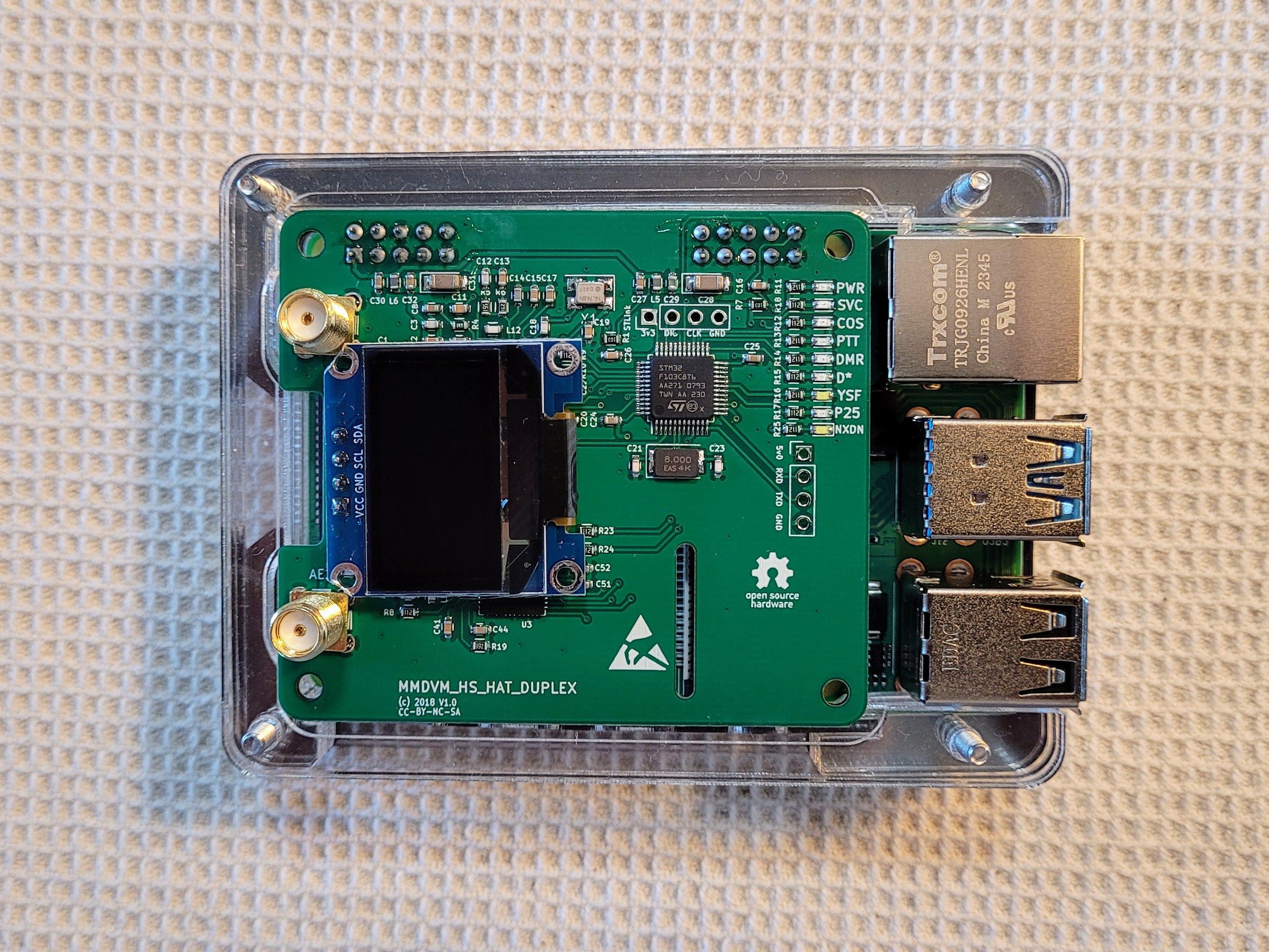
Continue to add clear layers. Attach the MMDVM modem before adding the other black layer. No soldering is required—the modem just “friction fits” on the RPi’s GPIO pins. Also, I’ve peeled the protective film off the small screen.
Add the black layer.

Add the top layer. It is clear with two holes for the antennas.

Add the four nuts and tighten the machine screws. I find it easiest to turn the assembly on its side and hold a nut with a fingertip while I tighten the screw. If the screw does not want to thread, try turning it the wrong way until you hear or feel a slight click. This indicates the screw threads have found the correct spot to mate with the threads in the nut (thank you, Dad, for this little piece of wisdom).

Take a moment to make sure there are no gaps between layers and that the ports line up with the holes in the port window. Check that each of the four screws is firmly tight but don’t overtighten them. I can’t tell you what overtight is. You only need the screws to be tight enough to hold the assembly together and to not come unscrewed as you move your hotspot from place to place.

Attach the two antennas, making them firmly finger tight. Don’t use a wrench on them— treat them gently.

The microSD card (see this resource for information on burning the WPSD image to the card) goes in with the card label visible when the hotspot is turned upside down.

Now you’re ready to attach an Ethernet cable and power up the new hotspot. (If you prefer/need to use wifi, see the W0CHP configuration tool for wifi.) If the image you wrote to the microSD card is good, you’ll see a message saying that WPSD is booting up.

Once WPSD boots up for the first time, you’ll see a notice on the LED screen that WPSD has not been configured. To learn how to configure your hotspot, refer to the WPSD user manual.

Once configured, your LED screen will look similar to this:

Configuring WPSD
OK, so your hotspot is connected to your local area network. That means you have an IP address.
First, make sure you can open the WPSD dashboard. I find it easiest to look in my router settings at attached devices to find the IP address of the hotspot. If you haven’t renamed the hotspot in the WPSD configuration settings, the dashboard may be accessible via http://wpsd.local. I never have luck with that, so I resort to entering the IP address in the URL space at the top of my browser. You may not need to do this if you see an IP address on the hotspot’s LED screen. Use that one.
General Configuration section
From the Dashboard, click Admin, then Configuration. At the top of the result page is the General Configuration section. Start there. In the examples below, I’m showing how my hotspot is configured. Compare that to the screens you see to help guide your configuration choices.

The DMR ID number is important. If you don’t have an ID number, go to https://radioid.net/ to get started on that item.
Your Radio Mode and frequencies matter, too. If you have a radio that only does simplex, then select Simplex for the Radio Mode. If you select Simplex, you'll be presented with a single radio frequency for both transmitting and receiving. My Yaesu FT5D can do split frequencies, so I’ve set my hotspot for duplex mode with separate TX and RX frequencies. Specifically, the hotspot transmits on 446.500 MHz, so my handheld radio is set to receive on that frequency. The hotspot receives on 441.500 MHz so my handheld radio is set to transmit on that frequency.
The Modem Type is important. You may have a generic modem that doesn’t clearly match one of the modems in the pulldown list. You need to select the correct modem. To find out how, review this article by Chip W0CHP. As long as you haven’t changed the login details for your hotspot, you can SSH to your hotspot’s IP address and authenticate as user pi-star with password raspberry.
Node Location & Info Settings section
The next section deals with the location of the node, your information, and whether to use an APRS gateway.
The software has a link to a service that can autodetect your latitude and longitude. It isn’t perfect but it will get you in the ballpark, and that may be all you desire. I like to use https://www.latlong.net/ where I simply enter my street address and out spits my location coordinates. Go to https://www.levinecentral.com/ham/grid_square.php to find your Maidenhead Grid Square the same way.
")
I see I missed setting my Country (ok, that is fixed).
You can also choose whether to display your hotspot location. Here’s my DVMEGA Cast device location at Mason Lake on the WPSD User Map:
")
You will have noticed that whenever you make a change in a configuration field, a notice appears at the top of the screen:

You can make all the changes in the various sections of this long page first and then click the Apply Changes button to record those in the software. You’ll get another notice that tells you the page will reload once the changes are complete. Wait for the page to refresh.

Radio/MMDVMHost Modem Configuration
In the Radio/MMDVMHost Modem Configuration section, you select the mode or modes you wish to use. (I prefer to only enable one mode at a time.)

MMDVMHost/Modem Display Configuration
In the MMDVMHost/Modem Display Configuration section, you select your modem type (“MMDVM Display Type”). I selected the 0.96” screen and changed no other parameters.

Yaesu System Fusion Configuration
Since I selected the YSF mode, I was presented with a YSF configuration section. I selected Kansas City Wide as the default startup reflector, meaning I don’t have to manually select it each time I start the hotspot.

Node Access Control
I did not change anything here.

The remaining sections address wireless configuration, remote access, and auto-updates and diagnostics. Since I’m plugged into a Ethernet cable, I did not enable wireless connectivity.
However, you can have WPSD scan for wireless networks and then select one. On the selection screen, you can also enter the password for a wireless network.
The size of this hotspot is very similar to the Hamspot 5 I featured last week:

I hope this long, step-by-step walk through the process of assembling and configuring a hotspot helps some fellow radio amateurs. This information should be enough to get you on the air with a homebuilt hotspot!
Miscellaneous
(I chuckle a bit at labeling this section “miscellaneous” since the Short Stack section near the top of the newsletter is often a hodge-podge of content items! But those items have some nexus with amateur radio. “Miscellaneous” items may not always relate to amateur radio at all.)
I went looking for a code editor that would install on my Windows ARM64 laptop. There are surprisingly few free, open source editors for my platform. Notepad++ is one of my go-to apps. I tried MS Visual Studio but it didn’t feel at all natural. It turns out that VIM (VI Improved) also has a GUI version called GVIM and it has an ARM64 installer. I’m using that for now, trying to get used to how it works.
I need a phone that my sister and daughter can use at the Lake House, especially in an emergency. Cell service out here is pretty sketchy, so I am trying a wifi phone, the Grandstream 816. I think I can configure it with one of the phone numbers I have at voip.ms. We’ll see. Seems worth investing some time, money, and energy in this test.
In 2018 and 2019, my employer built a new office and demonstration facility. During the construction phase in 2019, I was on site every day of every week to document construction, monitor what was happening, and interface with the general contractor/construction manager. This was challenging but it paid off several times when I identified significant problems that would have cost a lot of money to fix later. This week, I took a day off to tour the facility and grounds. I was extremely pleased to see that improvements have continued, enhancing and improving the original design. It’s a great place and space. One highlight is the newly landscaped plaza behind the building that is dedicated in my name. The best part was simply reconnecting with friends, getting lots of hugs, and catching up with great people. If interesting learn more about the Conservation Resource Center. You might also be interested in the other major project I helped move forward, the Eagle Creek Community Forest. At the bottom of the Eagle Creek Community Forest page, there are some great trail cam videos of wildlife from the cams I put out right after we purchased the property.
I’m waiting on a used MacBook Air laptop that was quite inexpensive, and the plan is to convert it to some flavor of Linux. Based on the testing I’ve done: probably Debian 13 “Trixie” will be my choice.
I also dug out my tiny SHARI node built on a Raspberry Pi Zero by Kits4Hams. I wanted to see how it sounded, compared to the Hamspot 5. Where I see the most difference between the two platforms is in the responsiveness of the device, especially when updating the system. But for regular AllStarLink radio traffic, they seem to perform pretty much the same. I’ll be running them side-by-side next week.
Closing
I’m looking forward to loading Linux on the MacBook Air. Maybe I’ll try dual booting it for a while.
My Lenovo ThinkStation P510 server stopped letting me remote into it. I’ve recovered it from Portland, Oregon and will work on it this week at the Lake House. Maybe it’s because it is running Windows 10 Pro, but I won’t know until I get it hooked up to a monitor and keyboard and see what’s happening. Fortunately, my data drive is separate from my operating system drive, so I can pick up an SSD drive and load a different operating system (Linux, anyone?) if needed.
With that I’ll close the channel and say 73 to all. Remember to touch a radio every day!

Thanks for the great review of building a hotspot from scratch. Chip should be honored about the WCHP-M17 fork as no one is trying to portray that as anything other than WCHP… that supports M17. Hi from Pacificon!
The CAST hardware and firmware only supports DSTAR, DMR and YSF. It’s never supported M17 (nor P25 and NXDN).
The DVMEGA Euronode, unlike the CAST, uses an actual MMDVM modem with RF. It has M17, P25 and NXDN capabilities with the right software.
They are two different/separate products.